

NXS-9700 User’s Manual
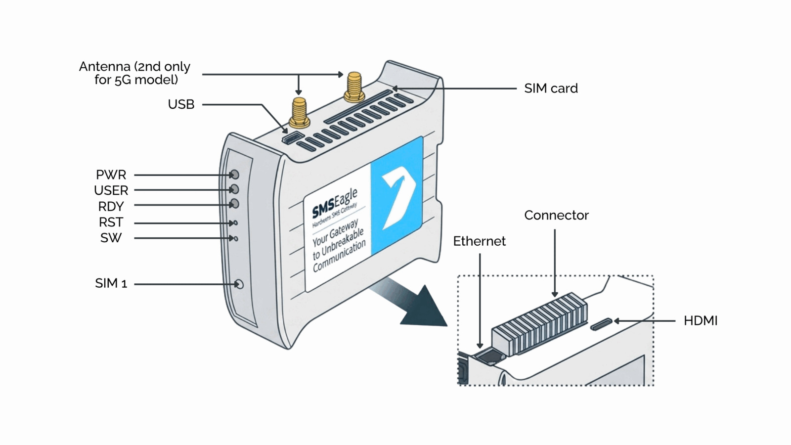
Connectors, Ports and LEDs
Element |
Label |
Description |
|---|---|---|
VCC Rev.3 Rev.4 |
VCC |
Power connector |
12-pole connector |
– |
4x digital Input, 4x digital output, 1x 1Wire, 1x 5V, 2x GND |
SIM Card Slot |
SIM |
SIM card slot |
HDMI port |
HDMI |
HDMI port (for debugging purposes only) |
USB port |
USB |
USB port (for debugging purposes only) |
Ethernet Port |
ETH |
Ethernet RJ45 port |
Antenna |
ANT |
Antenna socket |
Power LED |
PWR |
LED indicating power-on |
User LED |
USER |
LED for user application purpose |
SIM1,2 LEDs |
Modem 1,2 (optional) |
LED indicator for modem status |
Ready LED |
RDY |
LED indication device status |
Reset |
RST |
Switch for rebooting the device |
User Switch |
SW |
Switch for restoring to factory settings |