

Monitoring
This chapter covers the Monitoring section of the web interface: checking external hosts and services, reading digital I/O and physical sensors.
Network Monitor
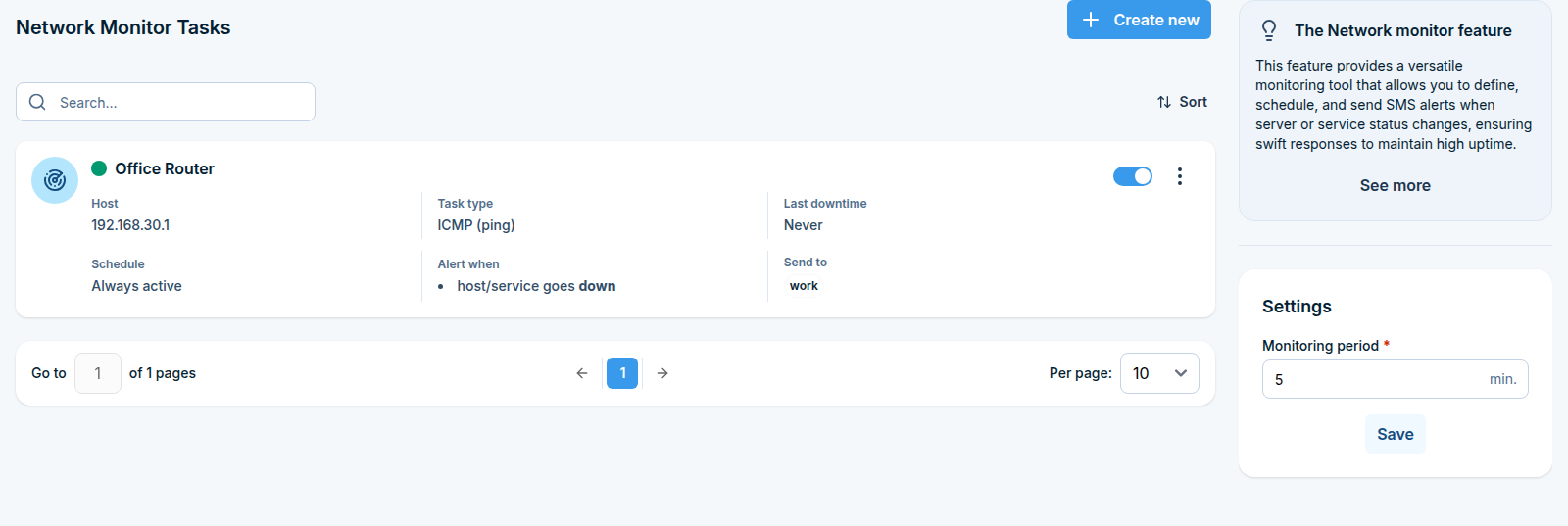
What this feature does
Network Monitor turns your SMSEagle into a small monitoring station. It checks servers, devices and services on a schedule and sends an SMS when something stops responding, comes back, or reports a value outside the range you expect.
It has three parts:
Page |
What it does |
|---|---|
Tasks |
The monitoring rules: what to check, how often, who to alert. |
Reports |
A history of downtime, filtered by date range and task, exportable to CSV. |
SNMP Traps |
Rules that turn SNMP traps sent to the device into SMS messages. |
Typical uses: alerting the on-call engineer when a production server stops answering pings, warning about a temperature reading from an SNMP sensor, or forwarding a UPS trap to a phone.
Before you start
The device must be able to reach the hosts you want to monitor. Check the network settings under Settings > Network first.
Recipients must be marked as Public in the Phonebook if you want to alert a group. Otherwise you can type plain phone numbers into the task.
For SNMP checks you need the community string and the Object ID (OID) you want to read. For Modbus checks you need the unit ID, the register and the function code.
Part 1: Tasks
Step 1: Open the Tasks page
In the sidebar, go to Monitoring > Network Monitoring > Tasks.
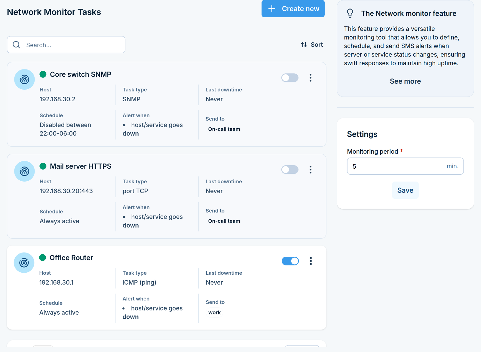
Each task in the list shows its host, schedule, task type, what it alerts on, when it was last down and who it notifies. A green or red marker tells you whether the host is currently responding.
Step 2: Set the monitoring period
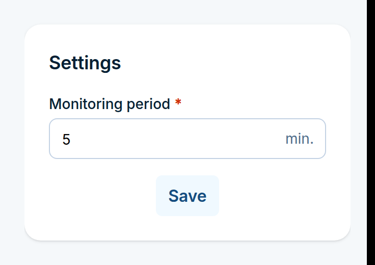
The Settings box on the right of the Tasks page holds one setting that applies to all tasks: Monitoring period, in minutes. This is how often the device runs the checks.
Enter a value and click Save.
Step 3: Create a task
Click Create new in the top right corner. The task form opens as a full page, divided into five sections.
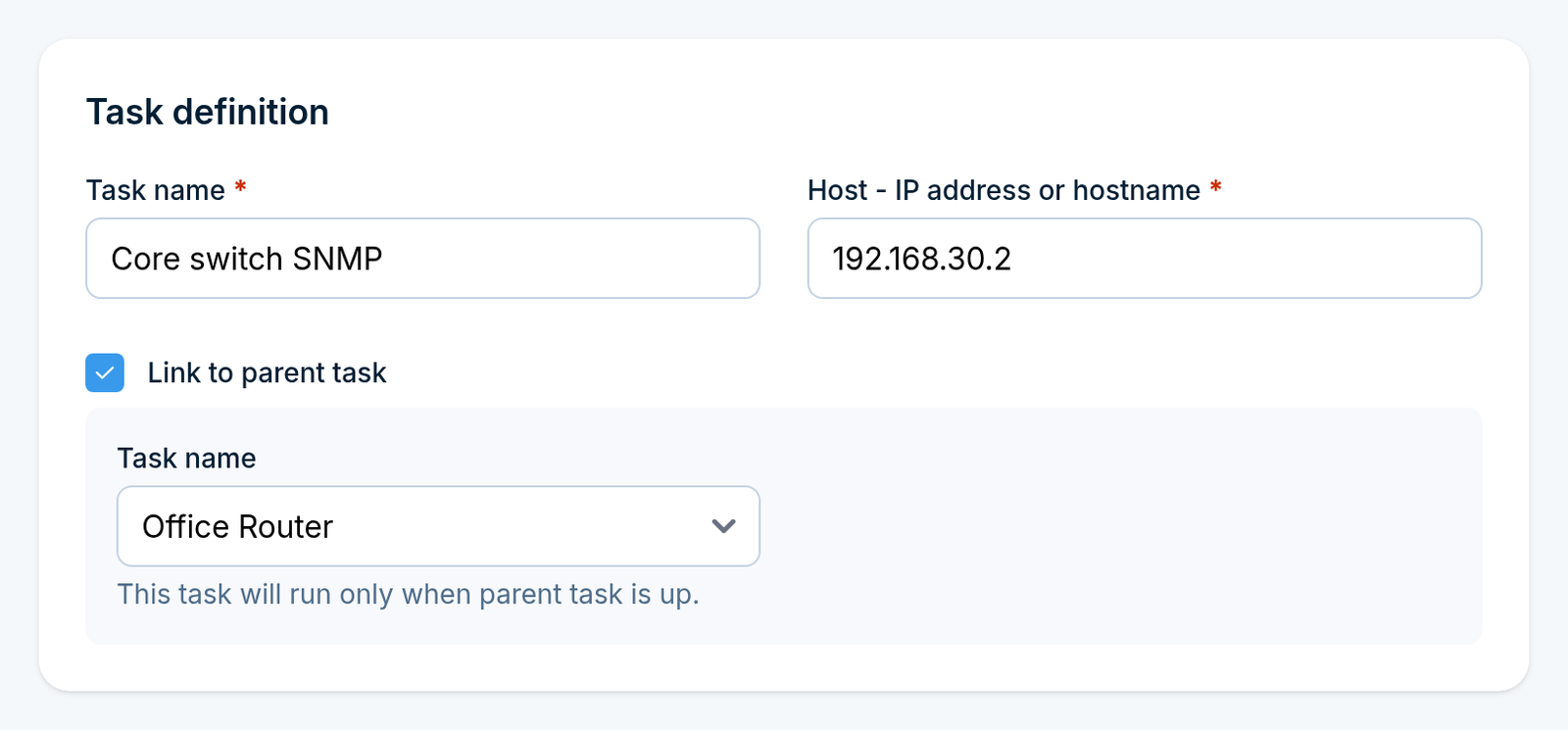
Task definition
Field |
What to enter |
|---|---|
Task name |
A descriptive name, maximum 100 characters, for example |
Host - IP address or hostname |
What to check, for example |
Link to parent task |
Tick this to make the task depend on another one. |
Task name (parent) |
Shown once the checkbox is ticked: the task this one depends on. |
A linked task runs only while its parent task is up. Use it to avoid alert storms: if the router in front of ten servers goes down, only the router task alerts, and the ten server tasks stay quiet.
Monitoring method
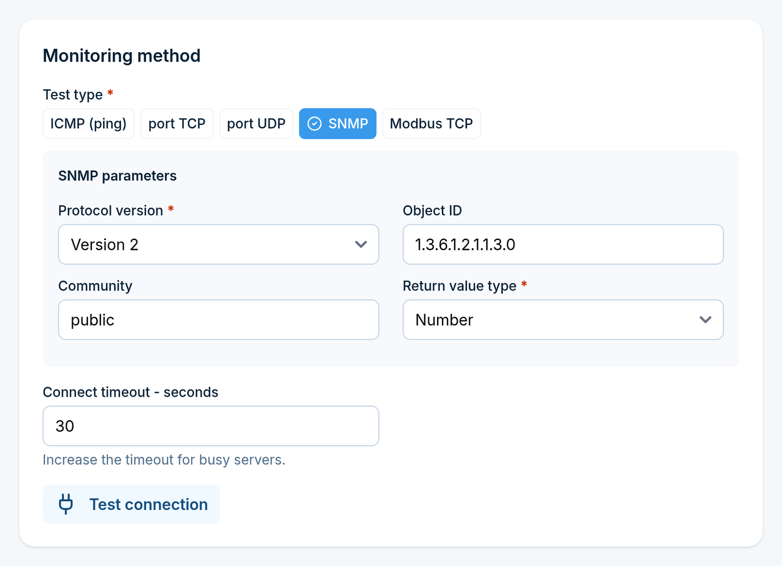
Pick the Test type, then fill in the parameters that appear for it:
Test type |
Parameters |
|---|---|
ICMP (ping) |
Number of requests - how many pings to send per check. |
port TCP |
Port - the TCP port that must accept a connection. |
port UDP |
Port - the UDP port to probe. |
SNMP |
Protocol version (1 or 2), Object ID, Community, Return value type (Number or String). |
Modbus TCP |
Port, Unit ID, Register, Function code (Read coils, Read Discrete Inputs, Read Holding Registers, Read Input Registers). |
Connect timeout - seconds applies to every test type. Increase it for busy servers that answer slowly; the default is 30 seconds.
Click Test connection to try the check straight away. The result appears next to the button, so you can confirm the host answers before you save the task.
Schedule
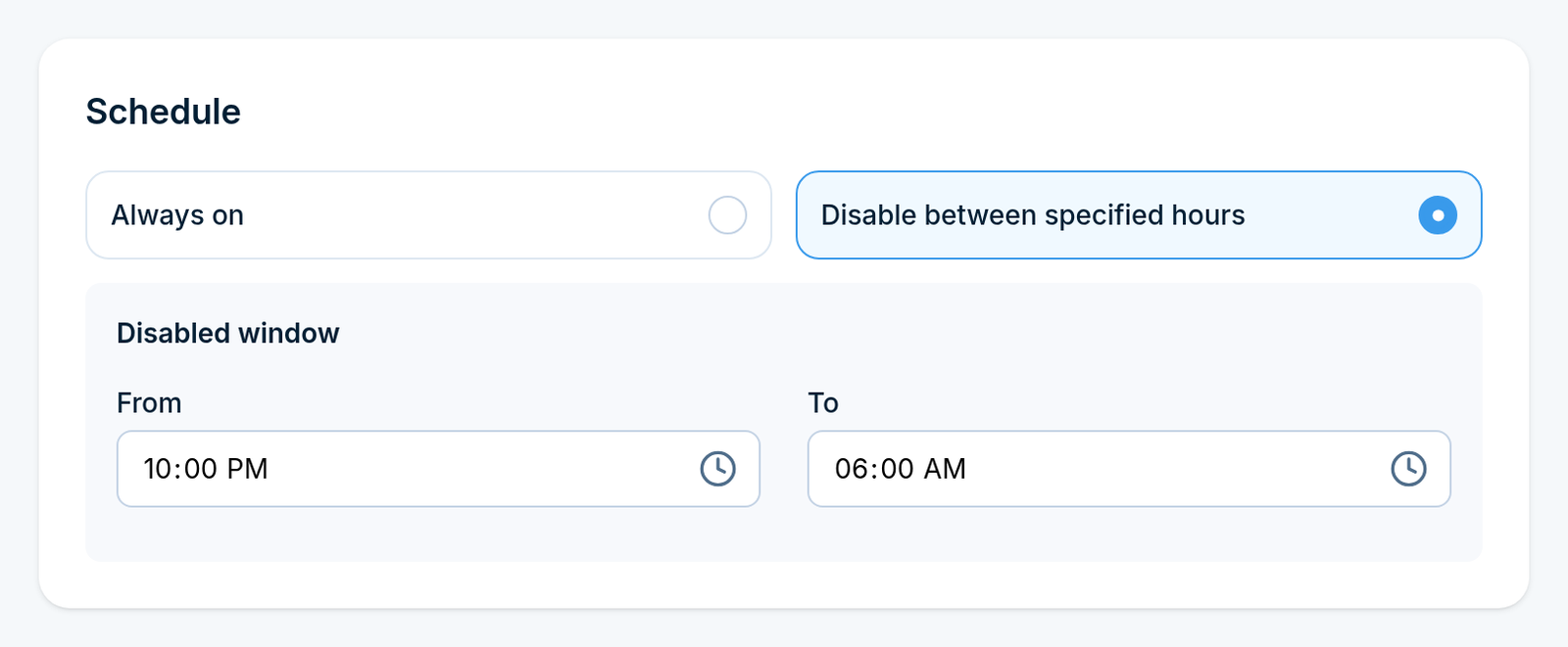
Choose Always on if the task should run around the clock, or Disable between specified hours and set From and To to create a quiet window, for example during a nightly backup that always takes the service offline.
Alert triggers
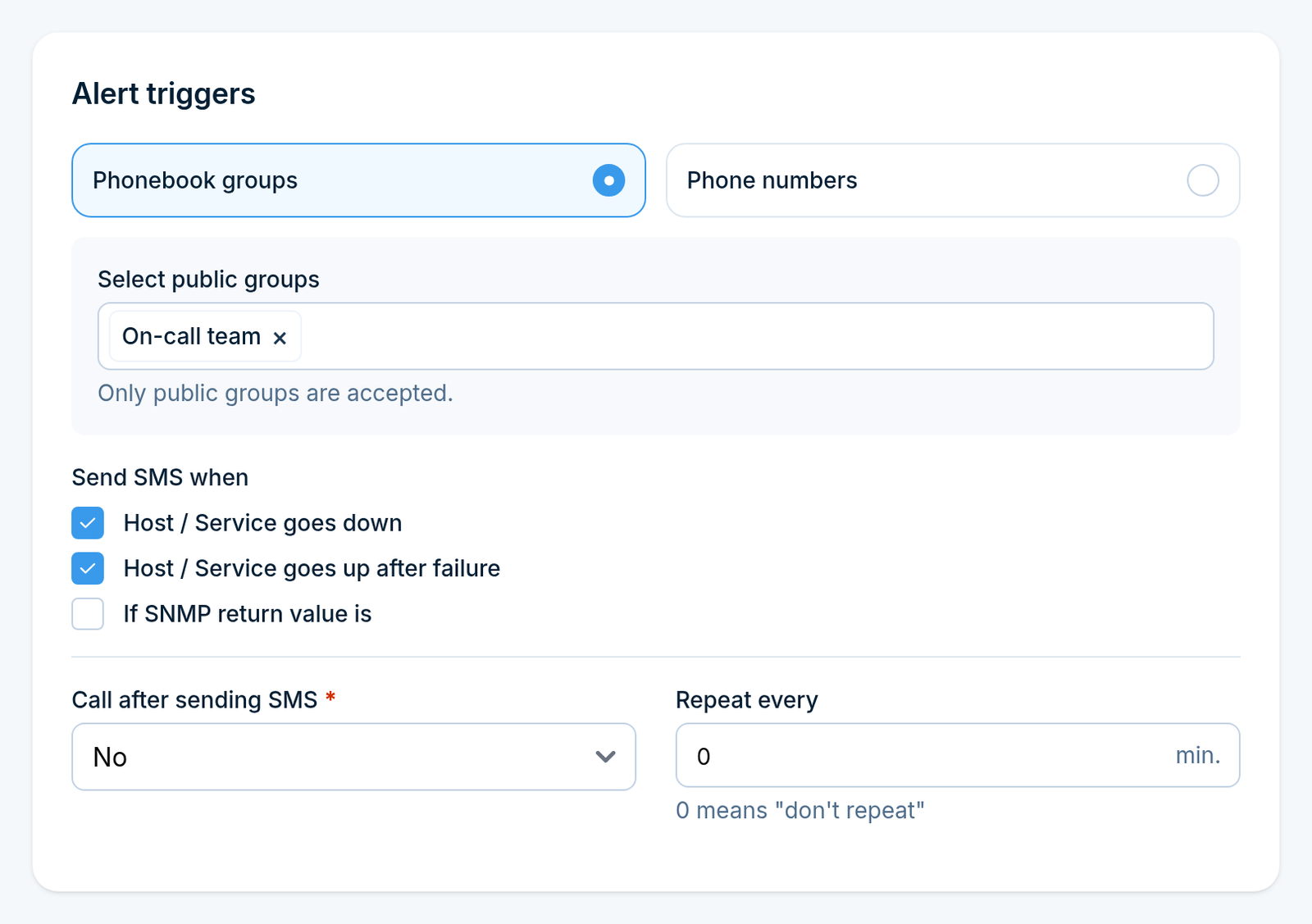
First choose who gets the alert:
Option |
What to enter |
|---|---|
Phonebook groups |
Select public groups. Only public groups are accepted. |
Phone numbers |
Type the numbers directly, separated by commas. Maximum 100 characters in total. |
Then tick at least one Send SMS when condition. Without one the task cannot be saved:
Host / Service goes down
Host / Service goes up after failure
If SNMP return value is - only for SNMP tasks. Pick an Operator (Equal to, Not equal to, Greater than, Less than, Contains, Does not contain) and a Value.
If Modbus return value is - only for Modbus tasks, with the same operator and value fields.
Two more settings close the section:
Call after sending SMS - also place a voice call. Options are No, Ring only, Yes - text to speech and Yes - text to speech (advanced), depending on your device model. With the advanced option you also pick a Voice model.
Repeat every - resend the alert every X minutes while the problem lasts.
0means send it once and stay quiet.
Message templates
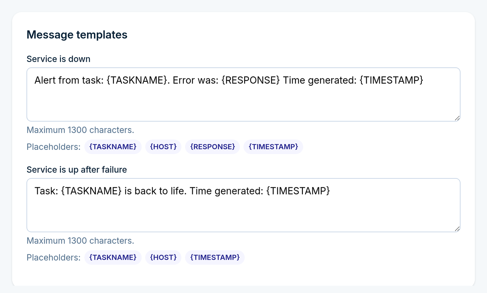
Write the text for each alert you enabled. Each message may be up to 1300 characters and can use placeholders:
Message |
Placeholders available |
|---|---|
Service is down |
|
Service is up after failure |
|
SMS Text (SNMP) |
|
SMS Text (Modbus) |
|
For example, DOWN: {TASKNAME} ({HOST}) at {TIMESTAMP} produces a message that says what failed,
where and when.
Click Create task. The task starts being checked at the next monitoring run.
Part 2: Reports
Go to Monitoring > Network Monitoring > Reports.
Generate a report
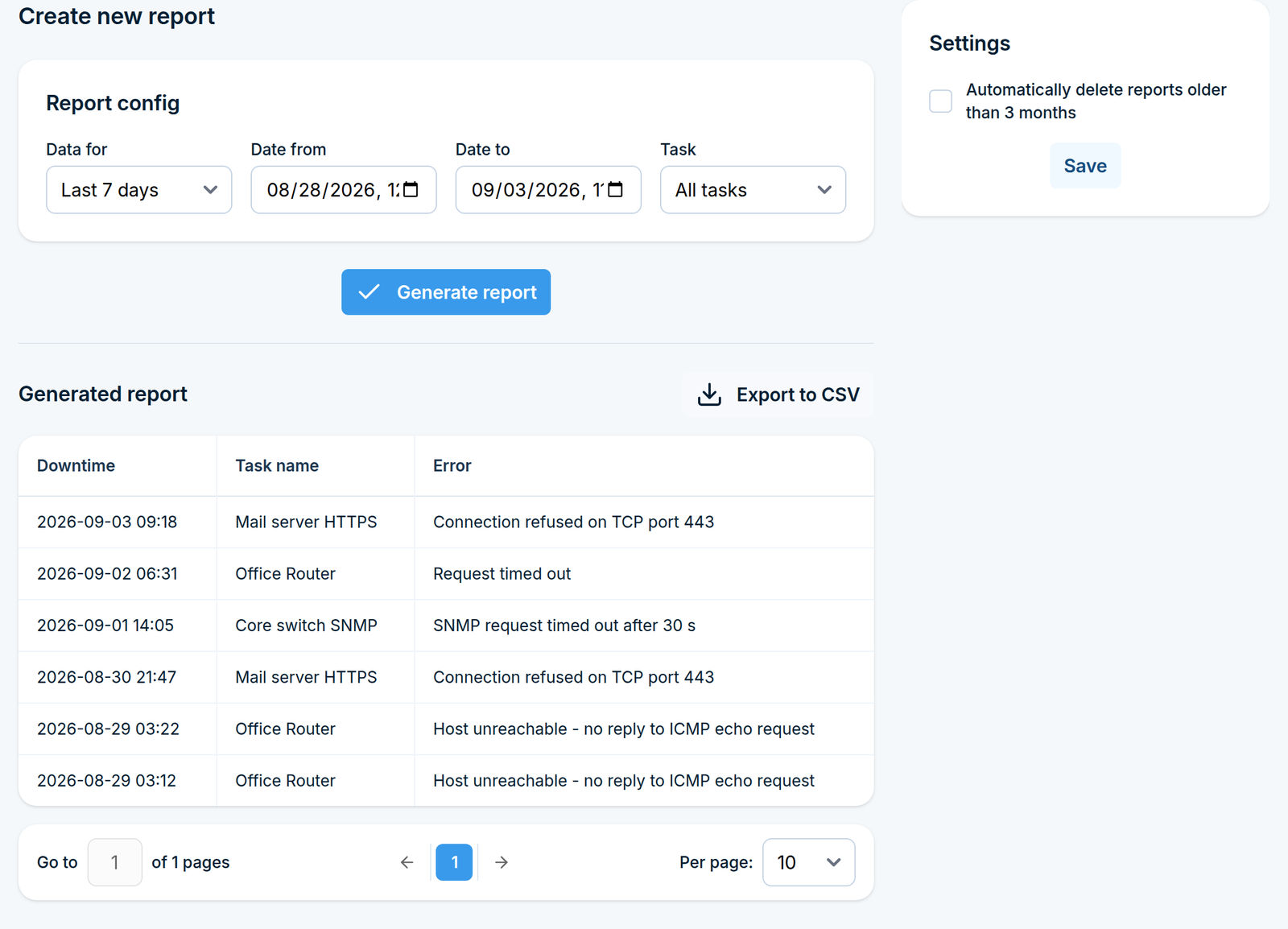
In the Report config box choose:
Field |
What it does |
|---|---|
Data for |
A ready-made date range. Choosing one fills in the dates below. |
Date from / Date to |
The exact range. Editing these switches Data for to a custom range. |
Task |
A single task, or All tasks. |
Click Generate report. The results appear below, listing the downtime, the task name and the error recorded for each incident.
Click Export to CSV above the results to download them.
Report retention
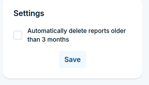
The box on the right holds one option, Automatically delete reports older than 3 months. Turn it on to stop the report history from growing indefinitely, then click Save.
Part 3: SNMP Traps
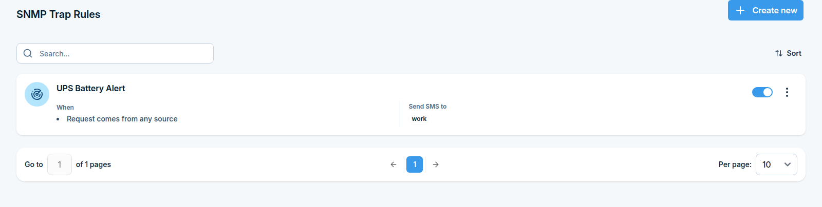
Tasks reach out and check things. SNMP trap rules work the other way round: another device sends a trap to the SMSEagle, and the rule turns it into an SMS.
Step 1: Open the SNMP Traps page
Go to Monitoring > Network Monitoring > SNMP Traps.
Step 2: Create a rule
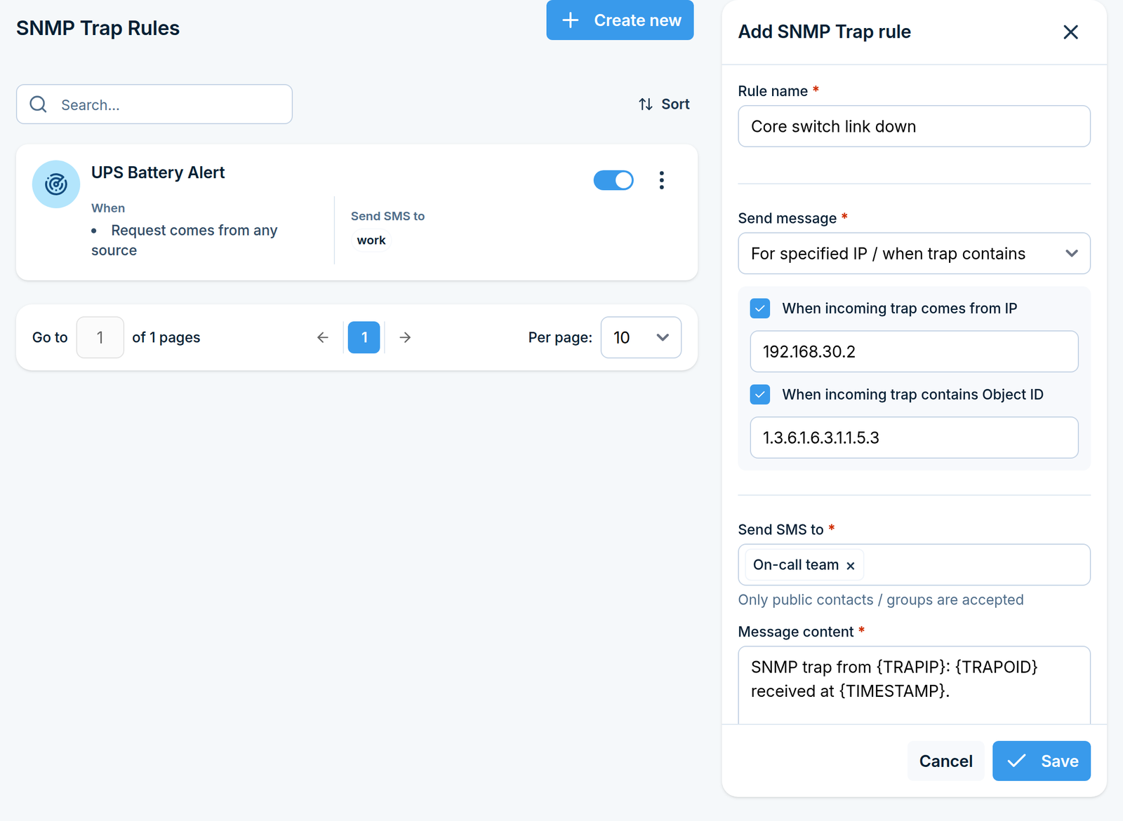
Click Create new in the top right corner. A side panel opens.
Name the rule
In Rule name, type something descriptive, for example UPS battery trap. Maximum 100
characters.
Decide which traps to act on
Choose Send message:
Option |
What it means |
|---|---|
Always send |
Every trap the device receives triggers this rule. |
For specified IP / when trap contains |
Only traps matching the conditions below trigger it. |
If you chose the second option, two conditions become available. You can use one or both, and a trap must satisfy every condition you enable.
When incoming trap comes from IP Tick this and type the IP address of the sending device.
When incoming trap contains Object ID Tick this and type the OID that must be present in the trap.
Choose the recipients and write the message
Send SMS to - select the contacts or groups. Only public contacts and groups are accepted.
Message content - the text to send, maximum 1300 characters. You can use these placeholders:
Placeholder |
Replaced with |
|---|---|
|
The name of the rule |
|
The IP address the trap came from |
|
The content of the trap |
Optional settings
Modem (multi-modem devices only) - send through a specific SIM card instead of the default.
Call after sending SMS - also place a voice call, with the same options as in tasks.
Click Save. The rule applies to traps received from now on.
How Network Monitor behaves
Tasks are checked on the shared Monitoring period, so a task cannot alert faster than that interval allows.
A “down” alert is sent once when the state changes, and then repeated only if you set Repeat every.
A task linked to a parent is skipped entirely while the parent is down, so its own alerts stay silent until the parent recovers.
If several SNMP trap rules match the same trap, each of them sends its own SMS.
Digital Input / Output
What this feature does
The digital inputs and outputs are the physical connector on the device that lets SMSEagle talk to the world outside the network:
Direction |
What it does |
|---|---|
Input |
A voltage change on an input port (a door contact closing, an alarm relay tripping, a UPS reporting a fault) makes the device send an SMS. |
Output |
An incoming SMS makes the device switch an output port on or off, so it can start a siren, open a gate or reset a machine. |
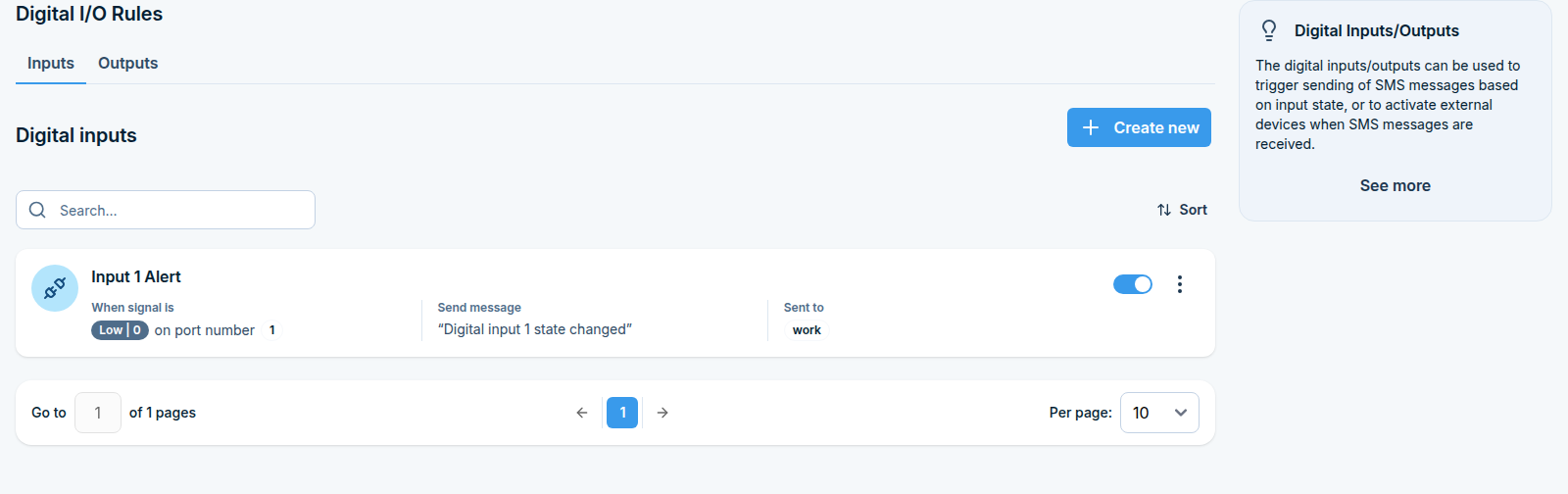
You configure this with rules. An Input rule says “when port 2 goes high, text the maintenance team”. An Output rule says “when an SMS containing OPEN arrives, set port 1 high for 5 seconds”.
Beside the rules there are two pages that show the ports themselves: Internal pins (the ports built into the device) and External pins (extra ports added through an io-bridge module).
Before you start
Check how many input and output ports your device model has, and wire your equipment to them. The port lists in the rule forms are built from your device model, so they only offer ports that physically exist.
The device must be able to send SMS. Check that at least one modem is connected and registered on the network.
Recipients of Input rules must be marked as Public in the Phonebook.
Where to find it
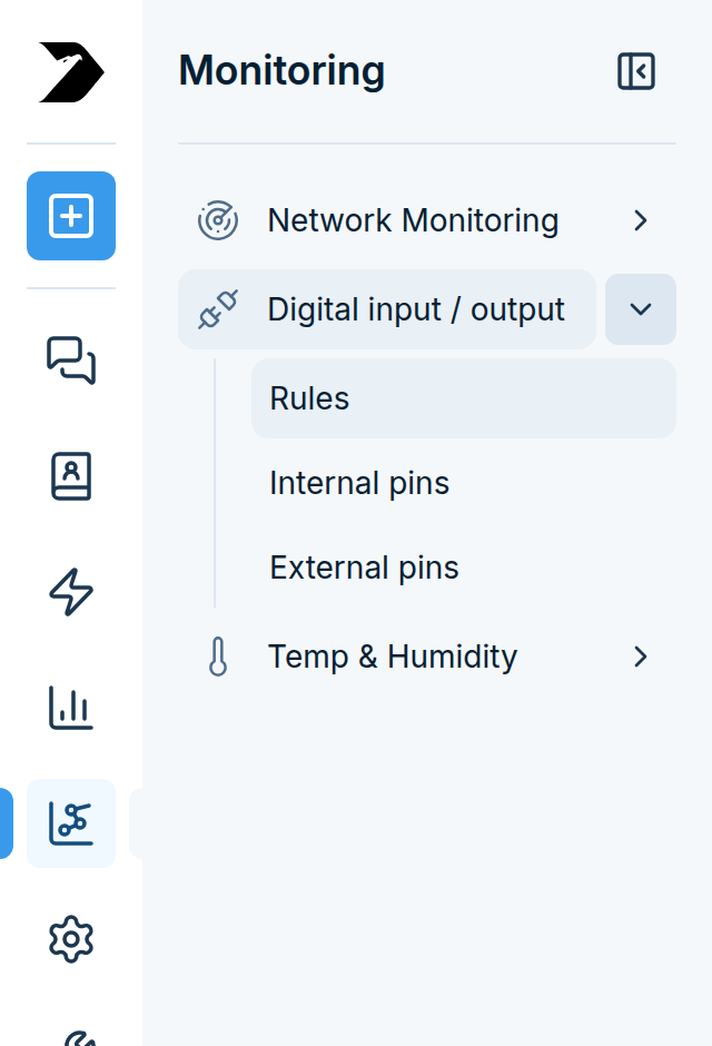
In the sidebar, go to Monitoring > Digital input / output. It has three pages:
Page |
What it is for |
|---|---|
Rules |
Create the Input and Output rules. This is where you spend most of your time. |
Internal pins |
See the live state of the built-in ports and turn the service on or off. |
External pins |
Define and control extra ports provided by an io-bridge module. |
Part 1: Input rules (input signal into SMS)
Step 1: Open the rules page
Go to Monitoring > Digital input / output > Rules and make sure the Inputs tab is selected.
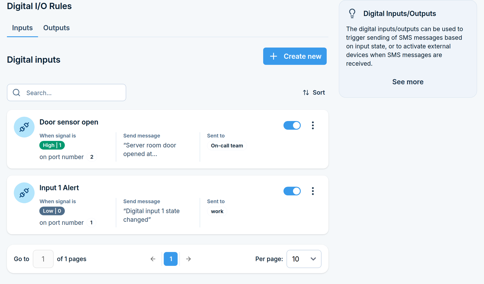
Step 2: Create an Input rule
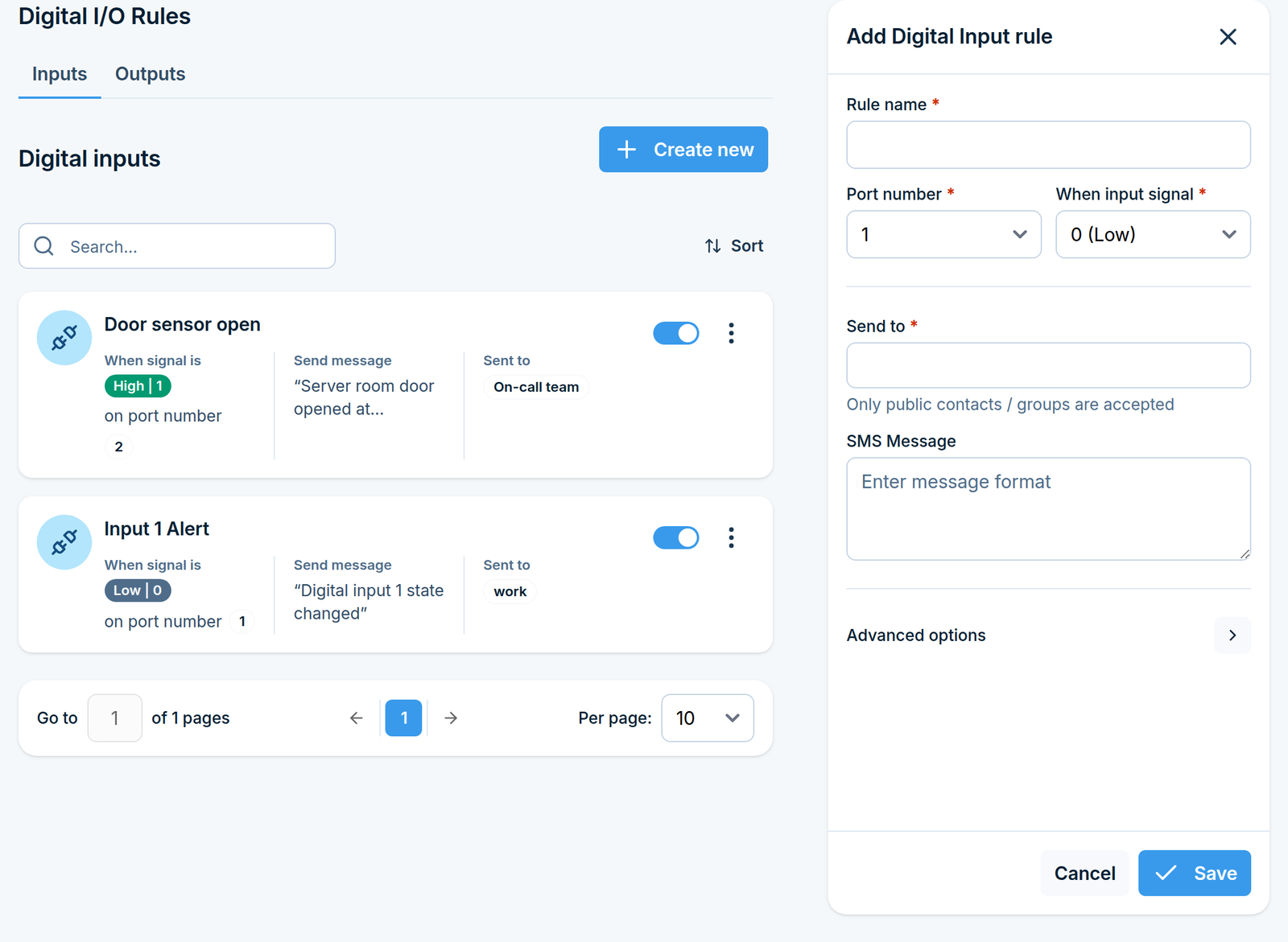
Click Create new in the top right corner. A side panel opens.
Name the rule
In Rule name, type something descriptive, for example Server room door opened.
Maximum 100 characters.
Choose the port and the signal
Field |
What to enter |
|---|---|
Port number |
The input port the equipment is wired to. External (io-bridge) ports appear in the list marked |
When input signal |
|
Pick the value that represents the alarm condition on your equipment. A normally-closed contact that opens on alarm usually needs 1 (High); a normally-open contact usually needs 0 (Low).
Choose the recipients
In Send to, select the contacts or groups that should receive the SMS. Only public contacts and groups can be selected here. This field is required.
Write the SMS text
SMS Message is the text that is sent when the rule fires. Maximum 1000 characters. The same text
goes to every recipient, so name the location or the machine in it, for example
ALARM: server room door opened.
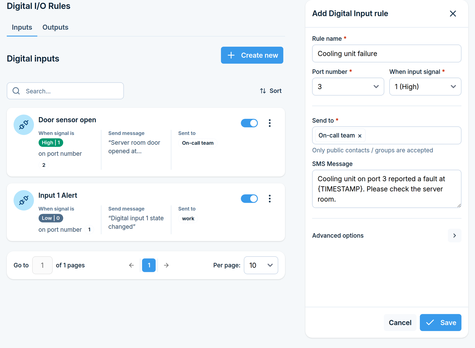
Advanced options
Click Advanced options to expand this section. You do not need it for a basic setup.
Call after sending SMS - also place a voice call to the same recipients. Options are No, Ring, Text-to-speech (TTS) and Text-to-speech (advanced), depending on what your device model supports. With the advanced option you also pick a Voice model.
Alert timeout - the number of minutes that must pass before the same rule may alert again.
0means no limit, so every signal change sends an SMS.
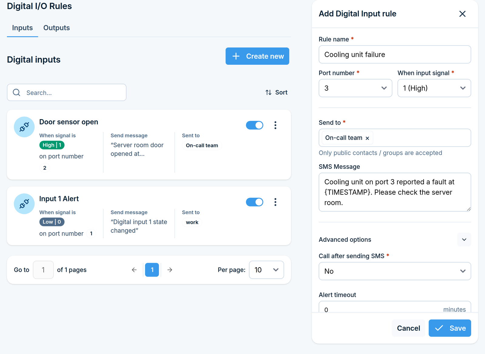
Set an alert timeout for noisy inputs. A contact that flutters, or equipment that trips repeatedly, can produce a burst of messages. A timeout of a few minutes keeps one real event to one SMS.
Click Save. The rule starts working on signal changes from now on.
Part 2: Output rules (SMS into output signal)
Step 1: Open the rules page
Go to Monitoring > Digital input / output > Rules and choose the Outputs tab.
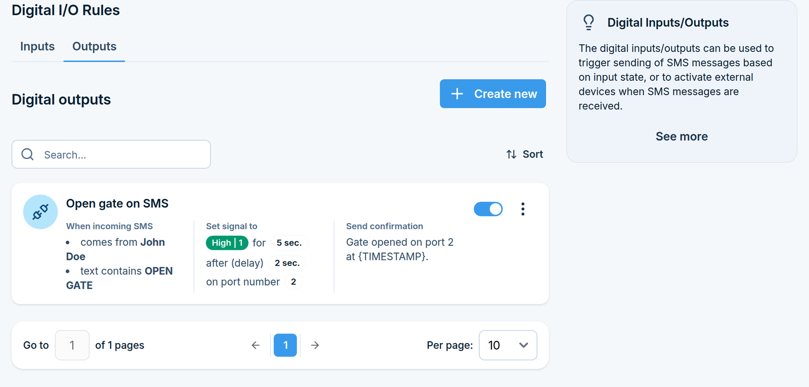
Step 2: Create an Output rule
Click Create new in the top right corner. A side panel opens.
Name the rule and pick the port
In Rule name, type something descriptive, for example Open gate on SMS. Maximum 100
characters. In Port number, choose the output port your equipment is wired to. External
(io-bridge) ports appear marked (Ext).
Decide which SMS messages trigger the rule
Choose Set for:
Option |
What it means |
|---|---|
All incoming messages |
Every incoming SMS switches the output. |
Specified sender / message |
Only messages matching the conditions you set below switch it. |
If you chose Specified sender / message, two conditions become available. You can use one or both. When you use both, a message must satisfy both.
When incoming SMS comes from Tick this and select the sender contacts or groups.
When incoming SMS text contains
Tick this and type the phrase in Text, for example OPEN. Tick Case sensitive if open
and OPEN should be treated as different.
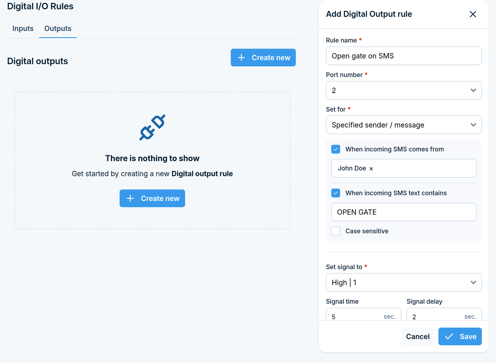
Restrict output rules by sender. An output rule switches physical equipment. Without a sender condition, anybody who knows your number can operate it.
Decide what the output does
Field |
What it means |
|---|---|
Set signal to |
|
Signal time |
How many seconds the port stays in that state before returning. |
Signal delay |
How many seconds to wait after the SMS arrives before switching the port. |
Advanced options
Click Advanced options to expand this section.
Send confirmation Tick this to send an SMS back to the sender after the output has been switched. The Message format field appears, maximum 1300 characters. You can build the text from placeholders:
Placeholder |
Replaced with |
|---|---|
|
The name of the rule that fired |
|
The output port number |
|
The signal the port was set to |
|
The signal time in seconds |
|
The signal delay in seconds |
For example, {RULENAME}: port {PORT} set to {SIGTYPE} for {SIGTIME}s produces a clear receipt for
the person who sent the command.
Call after sending SMS Also place a voice call, exactly as described for Input rules above.
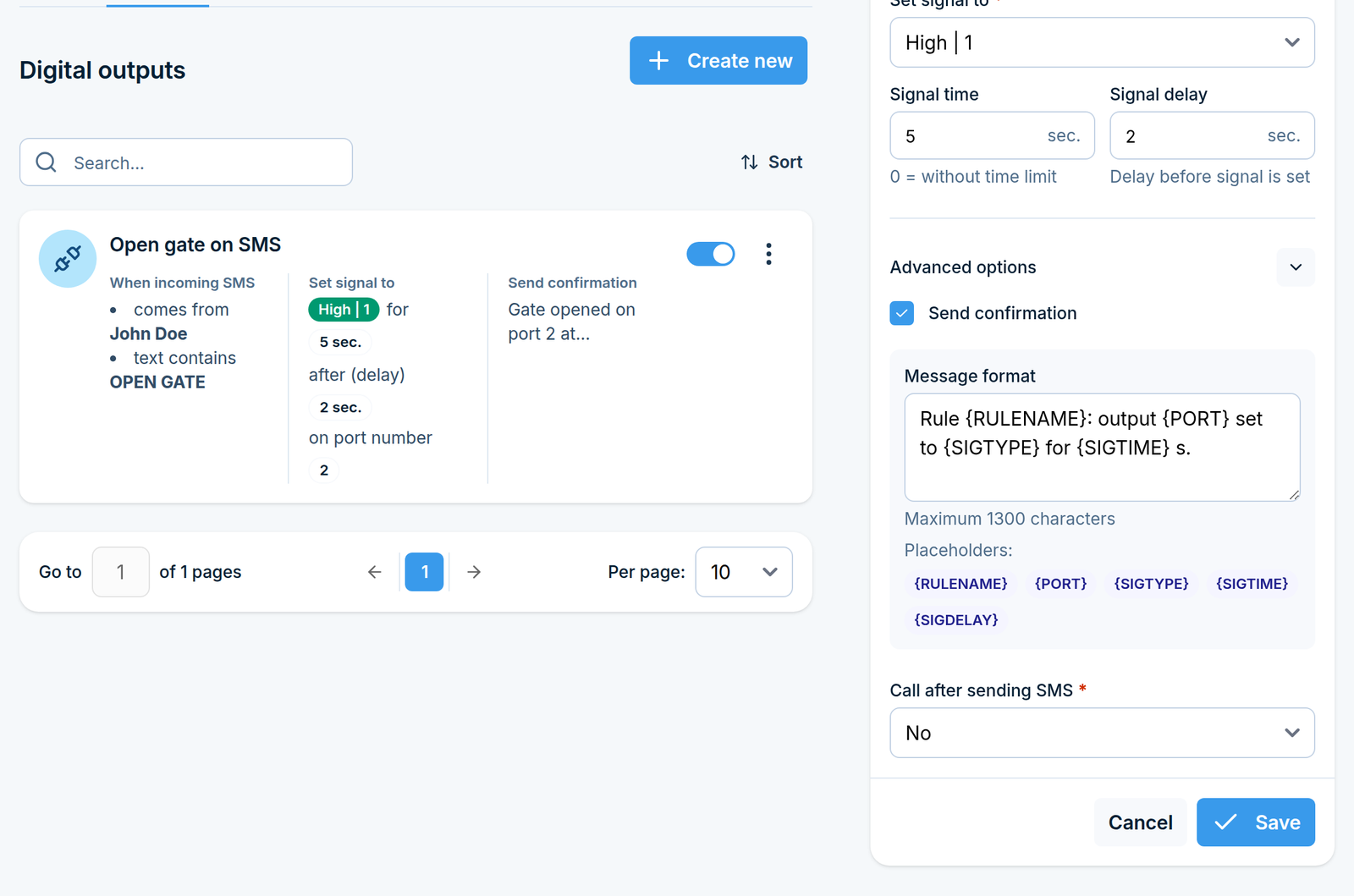
Click Save. The rule starts working on messages received from now on.
Part 3: Internal pins
Go to Monitoring > Digital input / output > Internal pins.
The page shows two tables, Inputs and Outputs, listing every built-in port with its current
state (0 Low or 1 High). This is a live read from the hardware, useful for checking your wiring
before you write a rule.
At the top of the page there is a Service enabled switch. It starts and stops the service that reads and drives the built-in ports. While it is off, Input and Output rules on internal ports do not work.
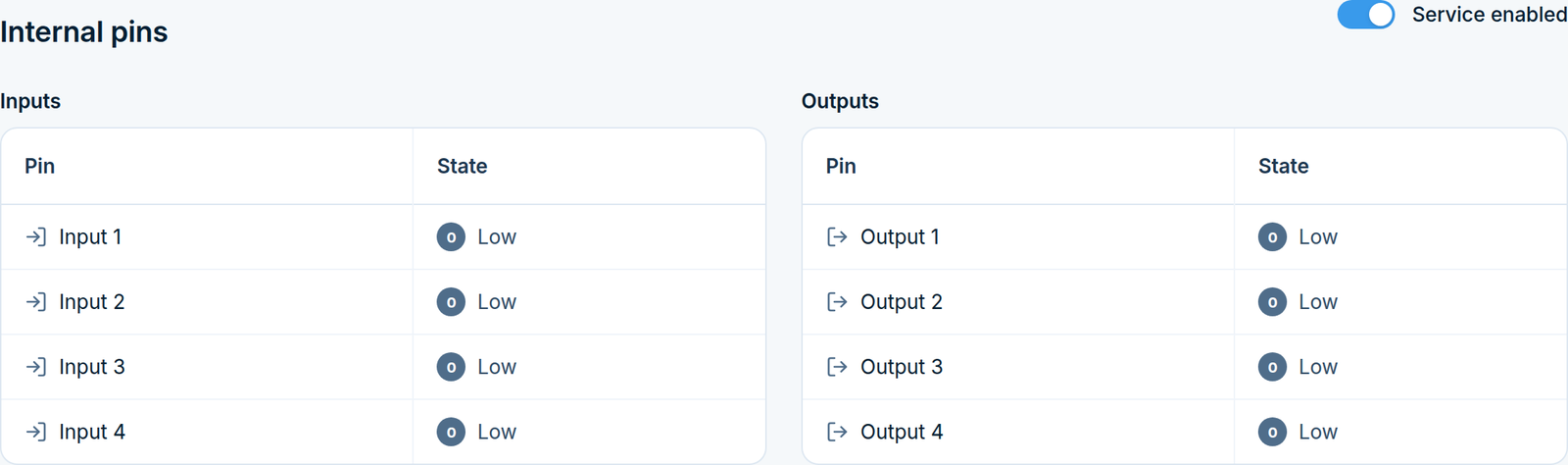
Internal pins with the service running. Every port here reads 0 Low because nothing is wired to it
Part 4: External pins
External pins are extra ports provided by an io-bridge module connected to the device.
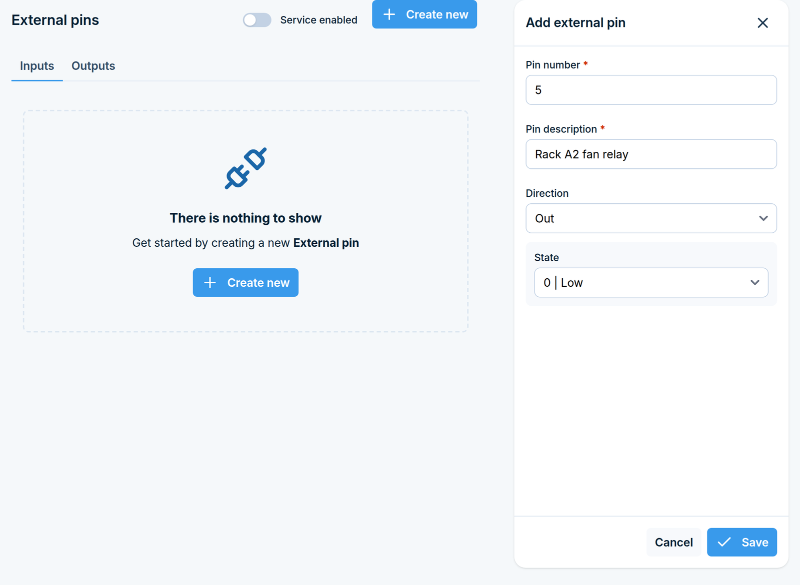
Go to Monitoring > Digital input / output > External pins. The page has an Inputs tab and an Outputs tab, plus a Service enabled switch that starts and stops the io-bridge service.
Add an external pin
Click Create new. A side panel opens.
Field |
What to enter |
|---|---|
Pin number |
The port number on the io-bridge module, for example |
Pin description |
A short name, maximum 64 characters. Only letters, digits and spaces are allowed. |
Direction |
In for a port you read, Out for a port you drive. |
State |
Only shown for Out pins: the state the port starts in, |
Click Save.
Use the pins
On the Outputs tab you can flip a pin’s state directly from the list.
On the Inputs tab the state is read-only, because the value is driven by whatever is wired to the pin.
Once defined, external pins also appear in the Port number lists of Input and Output rules, marked
(Ext), so rules can use them exactly like built-in ports.
How Digital I/O rules behave
Rules only act on events that happen after the rule was created and enabled. Use the switch next to a rule to pause it without deleting it.
If several rules match the same event, each of them runs, so one input signal can send several messages and one SMS can switch several ports.
The text condition on Output rules is a contains match, not an exact match.
Rules that use internal ports need the Internal pins service on; rules that use
(Ext)ports need the External pins service on.
Temperature & humidity sensors
What this feature does
SMSEagle NXS-line devices support temperature and humidity sensors connected to the device. Once a sensor is connected, the device reads it on a schedule, keeps a history of the readings, and can send an SMS when a value crosses a threshold you define.
The feature has three pages:
Page |
What it is for |
|---|---|
Reading |
Charts of the recorded values, with a CSV download. |
Alarms |
The rules that turn a reading into an SMS. |
Sensor settings |
The list of connected sensors, their names, and how often they are read. |
Typical uses: watching a server room, a cold store or a technical cabinet, and texting whoever is on call when it gets too warm or too damp.
Before you start
Connect the sensor to the device before configuring anything. The device finds sensors by scanning the hardware, so an unplugged sensor cannot be configured.
Recipients of alarm rules must be marked as Public in the Phonebook.
Where to find it
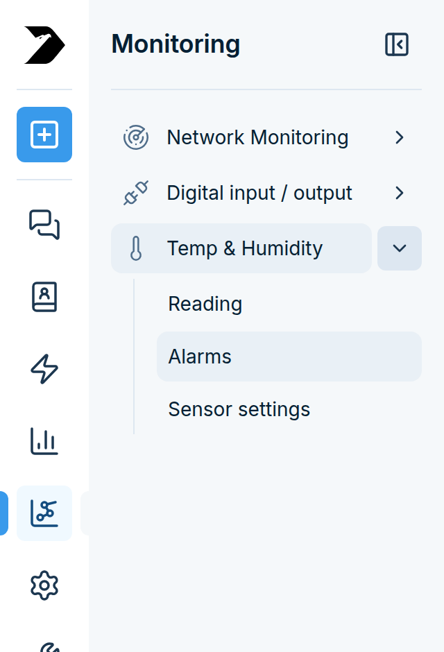
In the sidebar, go to Monitoring > Temp & Humidity. The three pages listed above appear under it.
Part 1: Add and name the sensors
Step 1: Scan for sensors
Go to Monitoring > Temp & Humidity > Sensor settings and click Scan for new sensors in the top right corner.
The device checks its inputs and adds anything it finds. The page reports either that new sensors were added, or that none were found.
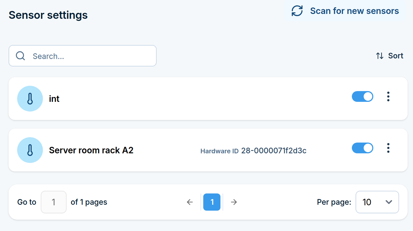
Each sensor in the list shows its Sensor name and its Hardware ID. The hardware ID is how the device identifies the physical sensor; it is not editable.
Step 2: Give the sensors meaningful names
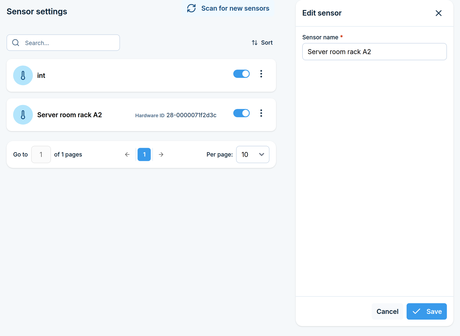
A freshly detected sensor is not named after the place it monitors, so rename it: click Edit next
to a sensor and type a Sensor name, maximum 255 characters, for example Server room rack A.
This name appears on the charts, in the alarm rules and in the CSV export, so it is worth doing before you build any rules.
Step 3: Manage the list
Each sensor has:
a switch to enable or disable it, which stops it being read without removing it,
an Edit action for the name,
a Delete action.
You can also tick several sensors and enable, disable or delete them together.
The internal sensor cannot be deleted. Devices with a built-in sensor always keep it in the list; disable it if you do not want its readings.
Step 4: Set the reading settings
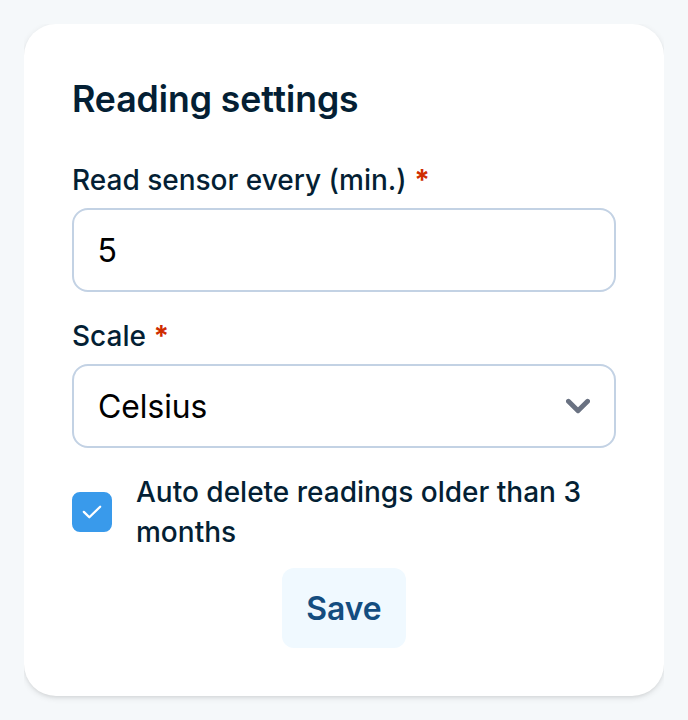
The Reading settings box on the right of the Sensor settings page controls how the sensors are read. These settings are global, they apply to every sensor:
Field |
What it does |
|---|---|
Read sensor every (min.) |
How often the sensors are read, from 1 to 59 minutes. |
Scale |
Celsius or Fahrenheit. Applies to the charts, the alarms and the export. |
Auto delete readings older than 3 months |
Keeps the reading history from growing indefinitely. |
Click Save.
Part 2: Alarm rules
Step 1: Open the Alarms page
Go to Monitoring > Temp & Humidity > Alarms.
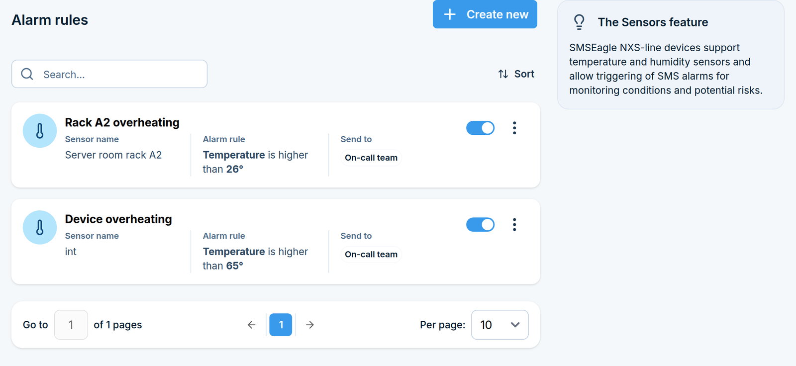
Step 2: Create a rule
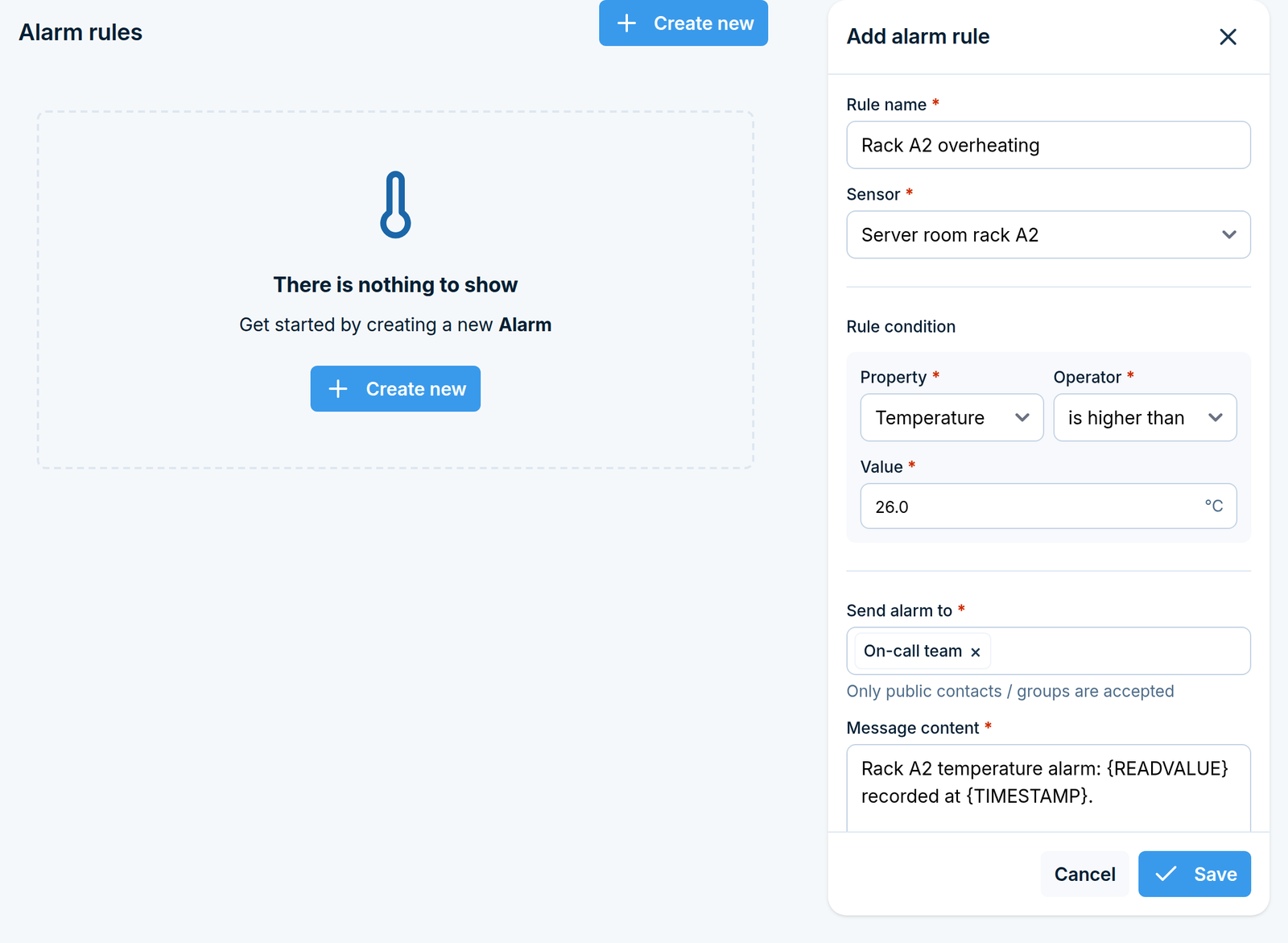
Click Create new in the top right corner. A side panel opens.
Name the rule
In Rule name, type something descriptive, for example Server room too warm. Maximum 100
characters.
Define the condition
Field |
What to choose |
|---|---|
Sensor |
Which sensor the rule watches. |
Property |
Temperature or Humidity. |
Operator |
is higher than or is lower than. |
Value |
The threshold, with one decimal place, for example |
The temperature threshold is read in the Scale you set in the reading settings, so a rule written for Celsius means something different after switching the device to Fahrenheit. Check your rules if you change the scale.
Choose the recipients
In Send alarm to, select the contacts or groups. Only public contacts and groups can be selected here. This field is required.
Write the message
Message content is the SMS that is sent, maximum 2000 characters. You can build it from placeholders:
Placeholder |
Replaced with |
|---|---|
|
The value that triggered the alarm |
|
When the reading was taken |
For example, ALARM: server room at {READVALUE} ({TIMESTAMP}) produces a message that says what was
measured and when, without anyone having to open the interface.
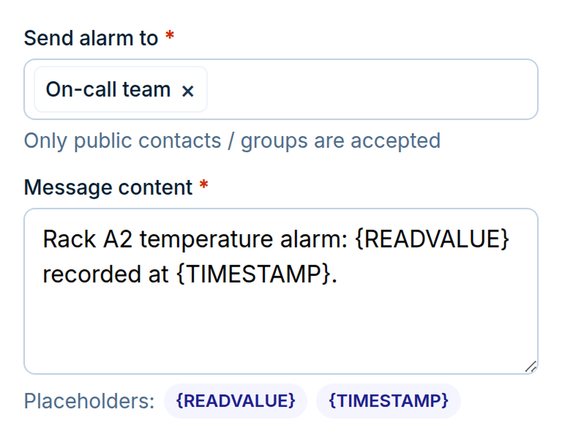
The badges below the field insert a placeholder at the cursor
Click Save. The rule is checked at every reading from now on.
Part 3: Readings and reports
Go to Monitoring > Temp & Humidity > Reading.
In the Report config box choose:
Field |
What it does |
|---|---|
Data for |
A ready-made date range. Choosing one fills in the dates below. |
Date from / Date to |
The exact range. Editing these switches Data for to a custom range. |
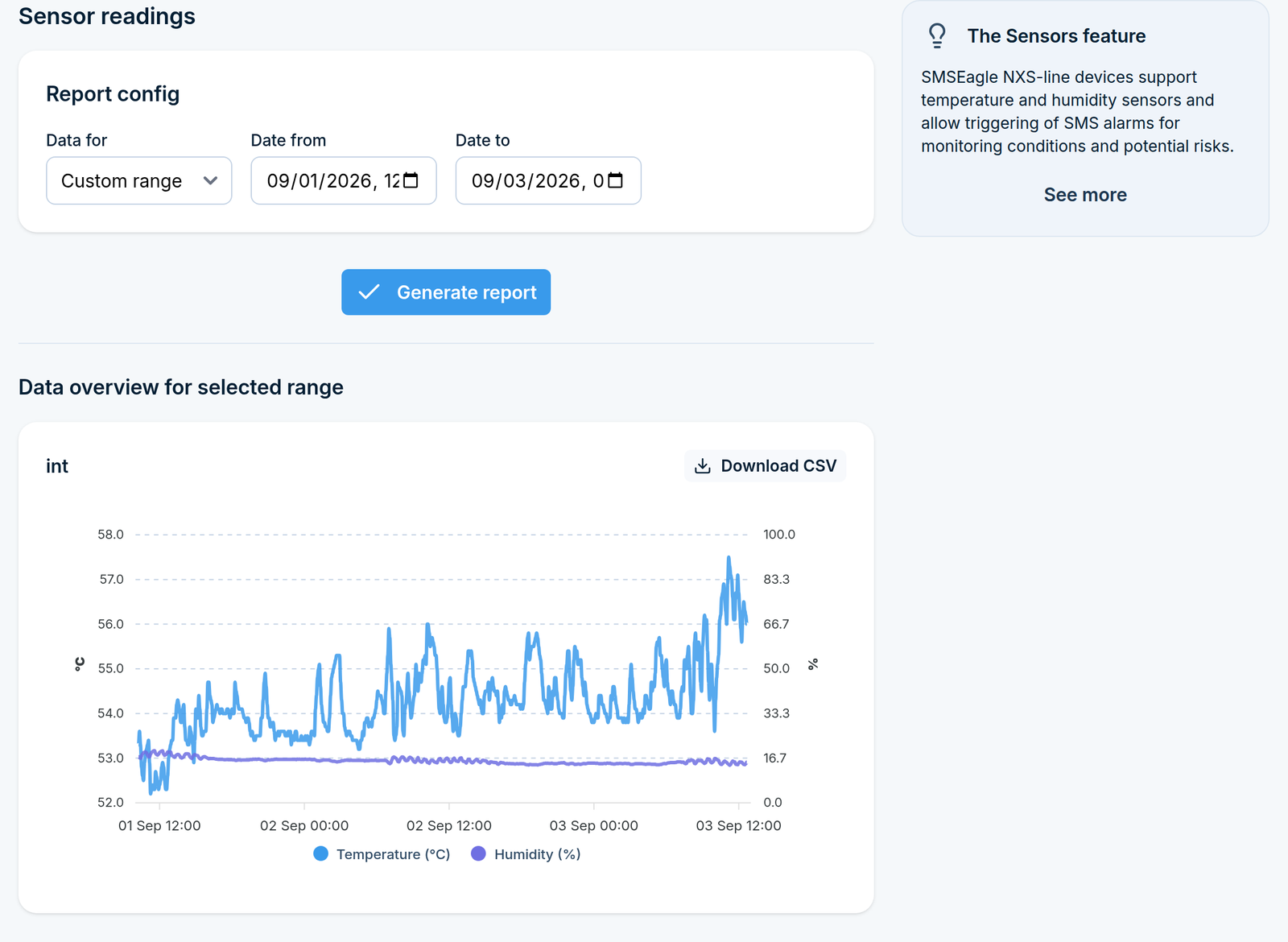
Click Generate report. Below, under Data overview for selected range, you get one chart per sensor, plotting its temperature and humidity over the period.
Each chart has a Download CSV button, which exports that sensor’s readings for the selected range.
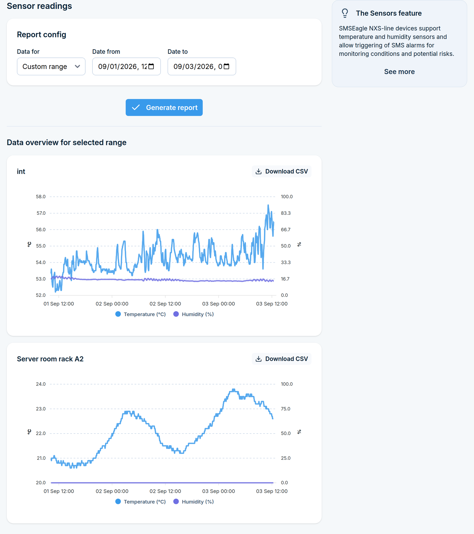
If the page says No sensors found, no sensor has been detected yet. Connect one and run Scan for new sensors on the Sensor settings page.
How it behaves
Alarms are evaluated when a reading is taken, so the reaction time depends on Read sensor every. A 15-minute interval means an alarm can be up to 15 minutes late.
A disabled sensor is not read at all, so alarm rules pointing at it stay silent.
If several rules match the same reading, each of them sends its own SMS.